many web pages and after a fair bit of testing I think this is a perfectly decent setup.
Please use as a guide, don't blame me if your Pi tries to go all Skynet on you.
Pin layout
GPIO pin connections looking from above your Pi with the micro power connection at the top left and
the GPIO in the top-right corner. The pin header numbers are in this order :-
Header #'s
Update: I moved header #12 (GPIO1) and #13 (GPIO2) to header #16 (GPIO4) and #18 (GPIO5) so
they can be used by a UPS PIco.
And with full detail the pin header layout looks like this:-
the GPIO in the top-right corner. The pin header numbers are in this order :-
Header #'s
1 2
3 4
5 6
7 8
9 etc...
Update: I moved header #12 (GPIO1) and #13 (GPIO2) to header #16 (GPIO4) and #18 (GPIO5) so
they can be used by a UPS PIco.
And with full detail the pin header layout looks like this:-
| 1. 3.3v ---> GPS VIN | 2. 5v |
| 3. SDA0 | 4. 5v |
| 5. SCL0 | 6. 0v ---> GPS GND |
| 7. GPIO7 | 8. TxD ---> GPS RX |
| 9. 0v | 10. RxD ---> GPS TX |
| 11. GPIO0 ---> OS LED (green) | 12. GPIO1 |
| 13. GPIO2 | 14. 0v ---> Button ground |
| 15. GPIO3 | 16. GPIO4 ---> Status LED (yellow / blue) |
| 17. 3.3v ---> Power LED (red) | 18. GPIO5 ---> Button |
| 19. MOSI | 20. 0v ---> OS & Status LEDs ground |
| 21. MISO | 22. GPIO6 |
| 23. SCLK | 24. CE0 |
| 25. 0v ---> Power LED ground | 26. CE1 |
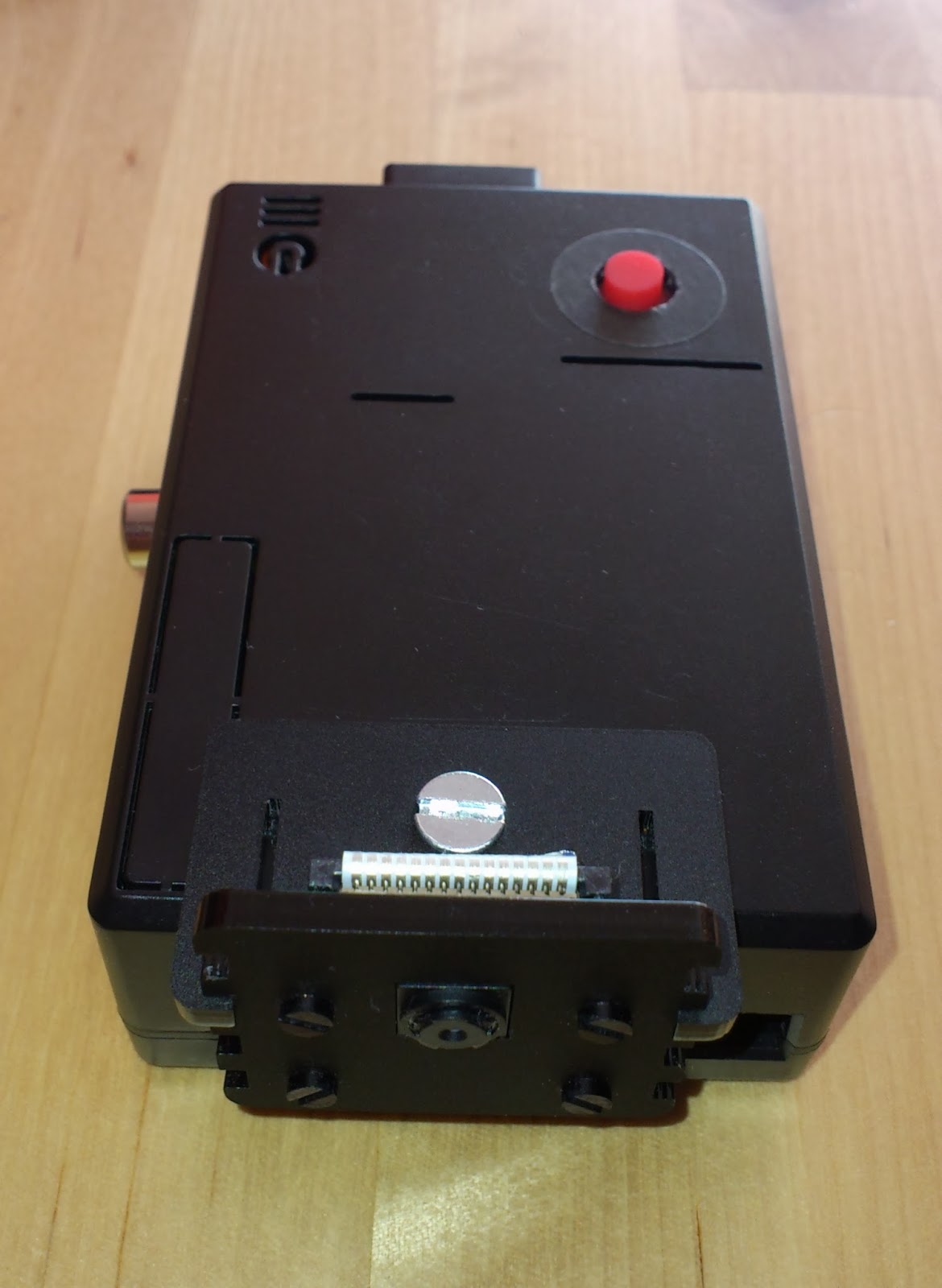
The Button
The shut down / reboot button is just a simple momentary push button. One pin on the button
is connected to GPIO 5 (header #18) with a 10k resistor in-between. The other button pin is grounded
to header #14.
If you are using the supplied scripts a program called "pwr_butt" constantly runs (with a small delay
between reads) monitoring GPIO 5. When the button is pressed the GPS, video recording and
monitoring scripts are all stopped. It then goes into a short loop and checks to see if the button has
been released or not. If it has been released the program initiates a power-off, if the button is still held
down after a few seconds the Pi is rebooted.
I used the wiringPi libraries to access the GPIO pins for the button and LEDs. See the GPIO section
of the install guide for further information.
For me the best location for this button was on top of the ethernet socket but consider your driving
position and how you will access the unit and place the button accordingly.

The GPS (The full Adafruit guide is here)
If you use an alternative GPS device for example a USB GPS then you can probably just install gpsd
and skip to the testing section. Also, if you are using the provided scripts do not forget to update the
global.rc file with your GPS device path.
If you are using a GPS with the Pi camera be aware that the Pi camera will interfere considerably
with the GPS signal. I would recommend keeping the Pi camera and GPS at least 20 centimetres apart.
Shielding the Pi camera's ribbon cable and the camera area with copper or aluminium foil will also
help slightly. Insulating the foil where required with isolation tape.
Power is taken from header #1 which is 3.3v, connect this to VIN on the GPS unit.
I used the ground (0v) from header #6 to connect to GND on the GPS.
Pi TxD (header #8) is connected to RX on the GPS unit.
Pi RxD (header #10) is connected to TX on the GPS unit.
I also installed the holder and optional battery.
Startup times can vary but I usually get a fix from a warm start within 15 seconds, a cold start normally
takes around 30-90 seconds.
Once the GPS unit is ready we need to free up the tty serial line. First make a backup of the cmdline
file just in case.
[root@carpi2 ~]# cp /boot/cmdline.txt /boot/cmdline.txt.org
Edit the command file and remove the "console=ttyAMA0,115200 kgdboc=ttyAMA0,115200" so it
looks like this...
looks like this...
[root@carpi2 ~]# cat /boot/cmdline.txt
root=/dev/mmcblk0p2 rw rootwait console=tty1 selinux=0 plymouth.enable=0 smsc95xx.turbo_mode=N dwc_otg.lpm_enable=0 elevator=noop
Next we need to stop 'getty' grabbing the connection to ttyAMA0.
[root@carpi2 ~]# systemctl disable serial-getty@ttyAMA0.service
I used gpsd to access the GPS unit. It worked straight away and is very easy to use. Install gpsd:
[root@carpi2 ~]# pacman -S gpsdAdd a rule so /dev/ttyAMA0 permissions are set correctly for gpsd automatically at boot time.
[root@carpi2 ~]# vi /etc/udev/rules.d/80-gpsd-perm.rules
# Change mode of ttyAMA0 so it is readable by gpsd
KERNEL=="ttyAMA0", SUBSYSTEM=="tty", DRIVER=="", MODE="0666"
Write and save the file.
Time for a reboot.
[root@carpi2 ~]# sync;reboot
Testing:-
If you want to have a quick check on whether your GPS is working you can just 'cat' the device:
[root@carpi2 ~]# cat /dev/ttyAMA0 (or the device path to your GPS device)
If it's working you should see a lot of lines of text beginning with $GP... appearing in the terminal
window. Ctrl+C to quit.
Start the GPS daemon using the device path to your GPS device (man gpsd for options)
[root@carpi2 ~]# /usr/bin/gpsd /dev/ttyAMA0 -F /var/run/gpsd.sock
You can check gpsd is interacting correctly with your GPS device like so:
[root@carpi2 ~]# /usr/bin/gpsd /dev/ttyAMA0 -F /var/run/gpsd.sock
You can check gpsd is interacting correctly with your GPS device like so:
Then enter: ?WATCH={"enable":true,"json":true}
If the daemon has connected successfully and things are working you should start to see some output.
To disable and stop the output type: ?WATCH={"enable":false}
Type Ctrl+] followed by 'quit' and return to exit this telnet connection.
[root@carpi2 ~]# cgps -s (without the -s you see all the information from the daemon)
Congratulations, the GPS is working! Here is an excellent page on GPSD with lots of information and
example programs on how to access things. The included program I wrote is called gps_logger. It is
a C program which connects to GPSD and after a GPS fix (or immediately if GPS_wait is set to 'no'
in the global.rc file) starts the pivid.sh or picam.py and motion_camera.sh scripts as required. It also
writes the gps_log file and gps_route file to /home/camera/logs by default.
The LEDs (see the GPIO section of the install guide to setup the gpio program)
For this last version I used 3mm flat top LEDs that do not require resistors. The green was a little
brighter than the red and blue so I added a resistor to help even things out.
The red LED is connected to pin header #17 (3.3v) and grounded (0v) on pin header #25.
It's connected to 3.3v so it comes on as soon as the Pi has power.
The green LED is connected to GPIO 0 (header #11) and grounded on header #20.
The blue LED is connected to GPIO 4 (header #16) and is also grounded to header #20.

My soldering iron is not the best but it does the job.
You can switch the LEDs off and on using the 'gpio' command:-
[root@carpi2 ~]# /usr/local/bin/gpio write 4 1
This will enable GPIO 4 and should switch on our blue (or yellow) status LED.
To disable GPIO 4...
[root@carpi2 ~]# /usr/local/bin/gpio write 4 0
Note
It may be best to first test the brightness of your LEDs on a breadboard so you can get the
level consistent between them.
LEDs have polarity, I do not believe you will damage them if they are connected the wrong way,
they just won't work. Usually the LED will have one leg longer than the other, the longer leg being
positive (+).
Finished
I taped the ribbon cable to the underside of the top cover but this makes it quite fiddly to feed the
cameras ribbon cable into the CSI slot whilst holding the top cover close. If you also tape the cable
cameras ribbon cable into the CSI slot whilst holding the top cover close. If you also tape the cable
make sure you leave enough slack to be able to feed the cable into its slot and lock it in place.


Hi,
ReplyDeleteThanks for this tutorial!!
I cannot open the pwr_butt file in nano. It displays gibberish and nano gives this message:[read 75 lines (Converted from MAC format)] and vi give this message [Incomplete last line][Converted]
Hi Leon,
ReplyDeleteGlad you liked the guide. The pwr_butt program was written in C so I could use milliseconds as the delay time in-between checking the button state and so you will not be able to view or edit it. Most of the settings it uses can be changed in the global.rc file though. Are you looking for something specific or just interested in how it works?
Regards,
Alan.
Hi Alan,
DeleteI am just interested in how the power button program is working in C because all the power button examples I've seen so far is done in python.
I'm waiting for my pi camera and then I'm going to use your guide and start playing.
Thanks again,
Regards
Hey Leon,
DeleteBelow is the old basic C code for the pwr_butt program, I haven't tested it recently but it should work. It's very easy using the wiringPi libraries for GPIO control. If you do compile it don't forget to add the library: gcc pwr_butt.c -lwiringPi
(replace the quotes with < and > on the includes)
// pwr_butt.c
#include "stdio.h"
#include "stdlib.h"
#include "unistd.h"
#include "signal.h"
#include "wiringPi.h"
#include "sys/types.h"
#include "sys/reboot.h"
#include "linux/reboot.h"
// Defaults
int button_gpio = 2;
void setup (void)
{
if (geteuid () != 0)
{
fprintf (stderr, "Need to be root to run.\n");
exit (0);
}
if (wiringPiSetup () == -1) exit (1);
pinMode (button_gpio, INPUT) ;
pullUpDnControl (button_gpio, PUD_UP) ;
printf("[pwr_butt]: Started.\n");
}
void waitButton (void)
{
int count;
printf("[pwr_butt]: Button GPIO %d is active.\n", button_gpio);
// Loop with small millisecond delay until button state changes
while (digitalRead (button_gpio) == HIGH) delay (100);
printf("[pwr_butt]: Button GPIO %d has been pressed.\n", button_gpio);
// Another small loop. If the button is released then halt else reboot
for(count=0;count<=4;++count) {
if(digitalRead (button_gpio) == HIGH) {
printf("[pwr_butt]: Halt.\n");
reboot(RB_POWER_OFF);
// reboot(RB_HALT_SYSTEM); / reboot(LINUX_REBOOT_CMD_HALT); / reboot(LINUX_REBOOT_CMD_POWER_OFF);
exit(0);
}
delay(500);
}
printf("[pwr_butt]: Reboot.\n");
reboot(RB_AUTOBOOT);
// reboot(LINUX_REBOOT_CMD_RESTART);
exit(0);
}
int main (void)
{
setup ();
for (;;) waitButton();
}
Thanks Alan,
DeleteRegards
Leon Smit
Hey, if you're going to compile it yourself, don't forget that you will need to include the "-I/usr/local/include -L/usr/local/lib -lwiringPi" at the end so the full command should look like this:
Deletegcc -o pwr_butt pwr_butt.c -I/usr/local/include -L/usr/local/lib -lwiringPi
Awesome, awesome project and instructions! Thank you very much for taking the time to journal it all down.
Regards,
Jay
Hi Jay,
DeleteThanks for the advice and glad you like the project. It's been pretty interesting and always good to hear if people find it useful too.
Cheers,
Alan.
Your "C" code has me jonesing,[withdrawal symptoms], as I've not written a line in a long time!
ReplyDeleteI know about 20+ languages, but straight C was easily my favorite, and by FAR! I fell in love with its pointer notation and it's tightness on memory when deal with 3 and 4 dimensional arrays! I'd probably do it for free even though they used to pay me ~$80 / hour in the 'good ole days'! LOL!
Can you imagine making 15-25 THOUSAND dollars a month to do what you LOVE? (Then they torched the balloon with cheap Indian and Chinese programmers, along with our entire economy, but that's another story!)
Anyway, thanks for the stuff on the Pi a very cool little box, indeed!
Back to YOUR business: Is arch linux still far and away better or has rasbian, the debian version, finally caught up?
ie: Would you still choose arch? Perhaps they have some cool talent the others don't have?
Thanks for any input!
Regards from cali,
T
Hi there, the main C program started out as small test for the GPS connection but then turned into a sprawling mess that controls everything. So often the way. To be honest it could really do with a rewrite. I also really like using C but I have not received recompense for any programs I have written. They are really for my own curiosity on how to do something or make life easier.
DeleteBut thanks, I'm really happy with how the dash cam turned out and the recording quality is pretty good for the cost.
Arch is still lightweight and quick but I did try a recent Raspbian build and was quite impressed. My personal preference is still Arch but I guess it's really about how comfortable you are with the command line. Sadly Arch has disappeared from the Pi download page which is a shame.
All the best. A/
Haven't coded in 30 years, but just bought a rpi and find this project interesting. Is your source code available anywhere, to help a newbie with details like the gps time date speed overlay? I'd like to try a simple project with GPS lat/lon alt speed time date overlayed with just the single RPI camera module, and a looping video rewrite on a 32 g SD (or larger), maybe with a small LCD to display status and current statistics. The thought on the looping write is to write 2 gig files with filename sequential based on date time, such as 20150815133000, when 2.5 gig space remains, the oldest file is deleted to make room for the next file to be written, perpetually. If a 64g is used, nothing needs to change, as the code would still periodically check when free space is 2.5g or less, and then delete the oldest 2gig video file.
ReplyDeleteHi, sounds like a good project. You can download the source code if you follow the link in the 'Scripts' section of the blog (unfortunately they do not have comments). The dashcam.sh program includes a subroutine to delete the oldest video files when a threshold is reached. You can modify the Pi camera video file names by editing picam.py (or pivid.sh). I used picamera for the text overlay in the picam.py script, you'll need to install python3 for it to work. Let me know if I can help further. All the best, Alan.
DeleteThank you. Gathering pieces and 32 gig SD cards.
DeleteReally interesting project. Gathering all the pieces for the dashcam
ReplyDeleteThanks Atharva, I had fun making it. I hope all goes well with you.
DeleteThis comment has been removed by the author.
ReplyDeleteI would like to install the camera on one side of the dash and the GPS receiver on the other side - with all other electronics several feet away, probably in the console between the seats. I haven't yet decided to do audio recording. Would this be possible with the components you have used?
ReplyDeleteAbsolutely. I have the Pi camera positioned at the top of the driver's side windscreen and the GPS unit over the front passenger side with the Pi itself in the middle. You can get very long ribbon cables to feed the Pi camera and easily extend the GPIO wires for the GPS. I am not sure if either of these have limitations on length so best check for your own piece of mind. Some people have used a bluetooth GPS with good results to avoid having a wired GPS. Things like power, USB cabling etc are easy to sort out.
DeleteI did test recording audio via my USB webcam which is located on the rear headrest and it works well but it is recorded to a separate file and so was not very useful for me. I usually leave it disabled.
Hello,
ReplyDeleteWonderful guide you have made! I have been working on this for a couple of nights and I am really happy with this. A couple of problems I have run into is in using the pwr_butt program. Seems like my PI (Original v1) has GPIO4 mode set to IN. If I manually set the mode to OUT the LED that I have wired for the Status comes on without issue. Is there a way around this. I also cannot get the momentary switch that I wired up to reboot or shutdown the RPi. I made a test python script for testing the button presses and when I press the button I do get output from the python script, so I know the button is working and wired to the correct pin on the PI. Is there something I am missing. I believe that all my parameters in the global.rc file are correct. I am currently not using a gps if that helps.
The following is the URL to the guide I used to write the python script to test the button presses. (http://razzpisampler.oreilly.com/ch07.html)
Hi There,
DeleteI'm glad you like the guide, not the most exciting read to be honest but hopefully it provides some good information. I have heard of this issue before on the Pi 1. With the original guide I made (for my Pi 1) I used different GPIO pins than what are used now and I think the newer pin choice does not work well with the Pi 1. I will do some testing when I can and get back to you.
Thank you for the link btw, it has some very nice information and tips.
Regards,
Alan.
It would seem the current binaries do not work with the Pi 1. If you try running them separately they probably fail. I have recompiled flash, pwr_butt & gps_logger for the Pi 1. Please download them from here: https://drive.google.com/open?id=0B3C9fv6-yJclZlNYVUhlZEQ4OWs and replace the old versions with them. Let me know how you get on.
DeleteLoaded the binaries you provided and it worked great. Thanks again.
ReplyDeleteAnyone tried the image on a Raspberry Pi Zero? I don't have a spare one to test it out.
ReplyDeleteHi guys,
ReplyDeleteAnybody look at this lately? Thinking of a dashcam system and wondering what route to go.